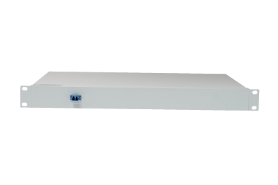
DCM dispersion compensation
In the field of optical fiber communication, Dispersion Compensation Module (DCM) (also called Dispersion Compensation Unit, DCU) is used to compensate dispersion, for example, to compensate dispersion in a very long transmission fiber. Usually, this module provides a certain dispersion (eg, normal dispersion in the 1600nm spectral region), although now there are also modules with tunable dispersion. Inserting the module into a fiber optic link is very simple as there are optical connectors at the input and output. A fiber amplifier can be used to compensate the insertion loss, for example, an erbium-doped fiber amplifier can be used in a 1500nm communication system. A dispersion compensation module is usually placed between two amplifiers.
The dispersion compensation module can be obtained by using the following techniques:
1. A common and simple method is to take a long piece of optical fiber, for example, dispersion-shifted optical fiber, and wind it on a bobbin with a diameter of 100-200mm. The optical fiber used can be optimized so that it can compensate the dispersion in the 100km long transmission fiber, and the insertion loss is only a few decibels.
2. Another more compact structure with low doping loss is the use of chirped fiber Bragg gratings. Large dispersion can be compensated by using relatively long (tens of centimeters) fiber gratings. Dispersion tuning is possible by varying the device temperature (built-in temperature gradient).
3. In WDM systems, phased arrays for some imaging are used.
Some important properties of dispersion compensation:
1. The core is the dispersion that can be provided, which depends on the length of the compensated transmission fiber and the type of transmission fiber. For example, dispersion-shifted transmission fibers require less dispersion compensation.
2. Dispersion slope (higher-order dispersion) strongly limits the available bandwidth, which is especially important in WDM systems. Depending on the type of transmission fiber, different dispersion slopes are required. The relatively high dispersion slope can make fiber design more difficult.
3. In some cases it is desirable for the dispersion to be tunable.
4. Insertion loss is caused by both absorption and scattering in the fiber, as well as contributions from splices and connectors. This loss needs to be kept as small as possible because they require high amplifier gain and introduce additional noise.
5. In some cases, optical nonlinear effects will also affect. Strongly dispersive fibers can minimize this effect, and very short fibers are sufficient.
6. In practical applications, compact structure is very important. Compensating fibers can be tightly wound, but this is also limited by bending losses.
At very high single-lane data rates, compensation for polarization mode dispersion is also required. This is more complicated, because it requires corresponding control of the polarization state of the signal light, and a reasonable adjustment of the time delay.

.jpg)

Comments
Post a Comment